Ben Eater 6502 Kit — Day 18 – Add disassembler to monito
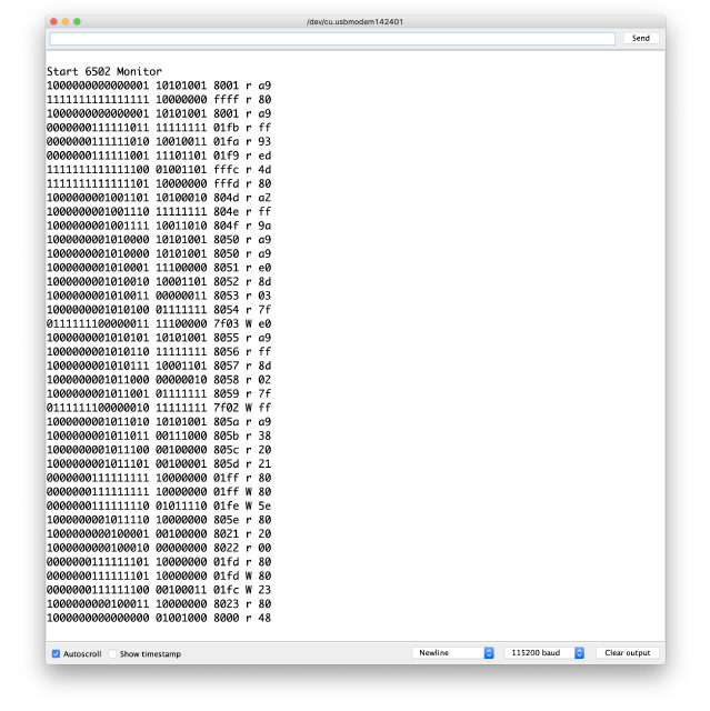
As the programs become more complex debugging becomes more difficult at well. All you have are hex codes which you need to interpret yourself:
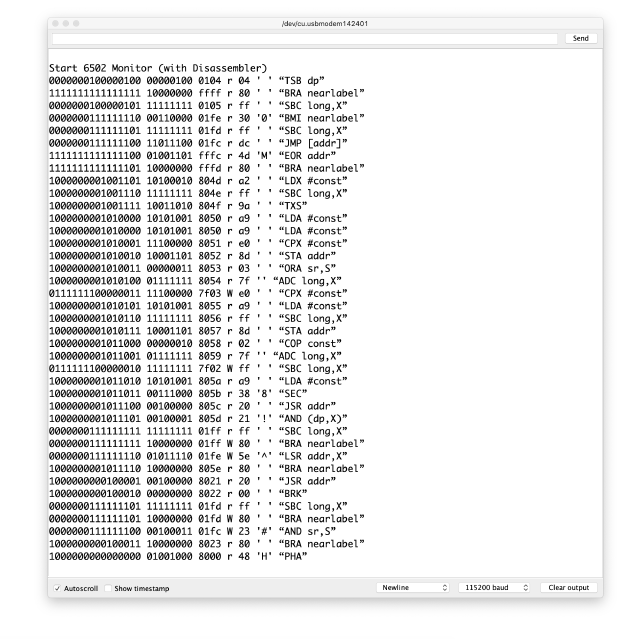
The Arduino is quite powerful and there is enough memory to do decode all 65C02 opcodes. Adding them as a huge array of string with all the opcodes is not a problem:
static String const Opcodes[] = {
    /* 00 => */ "BRK",
    /* 01 => */ "ORA (dp,X)",
    /* 02 => */ "COP const",
    /* 03 => */ "ORA sr,S",
    /* 04 => */ "TSB dp",
    /* 05 => */ "ORA dp",
    /* 06 => */ "ASL dp",
    /* 07 => */ "ORA [dp]",
    /* 08 => */ "PHP",
    /* 09 => */ "ORA #const",
    /* 0A => */ "ASL A",
    /* 0B => */ "PHD",
    /* 0C => */ "TSB addr",
    /* 0D => */ "ORA addr",
    /* 0E => */ "ASL addr",
    /* 0F => */ "ORA long",
…
    /* F0 => */ "BEQ nearlabel",
    /* F1 => */ "SBC (dp),Y",
    /* F2 => */ "SBC (dp)",
    /* F3 => */ "SBC (sr,S),Y",
    /* F4 => */ "PEA addr",
    /* F5 => */ "SBC dp,X",
    /* F6 => */ "INC dp,X",
    /* F7 => */ "SBC [dp],Y",
    /* F8 => */ "SED",
    /* F9 => */ "SBC addr,Y",
    /* FA => */ "PLX",
    /* FB => */ "XCE",
    /* FC => */ "JSR (addr,X)",
    /* FD => */ "SBC addr,X",
    /* FE => */ "INC addr,X",
    /* FF => */ "SBC long,X",
}; // Opcodes
And the printing them out is easy as well:
   auto Opcode = Opcodes[Data];

   snprintf (
       Output,
       sizeof Output,
       "%04x %c %02x %s",
       Address,
       Read_Write_Char,
       Data,
       Opcode.c_str ());
However, this is still not perfect as every clock cycle is displayed as an opcode. Even the write statement:
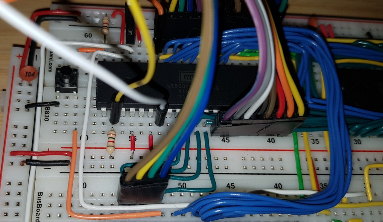
It would be even better if we could detect the actual opcode. And with the Western Design Center version of the 65C02 it’s actually possible as one of the pins, the SYNC (Synchronise with OpCode fetch) pin, outright tells us that the the instruction is fetched. So all we need it attach the SYNC pin to the Arduino:
And then chance the On_Clock function to make use of it:
/**
* executed at every clock pulse of the monitored 6502.
*/
static void On_Clock ()
{
   auto Address = A.Read ();
   auto Data = D.Read ();
   auto Read_Write = digitalRead (RWB) == HIGH;
   auto Sync = digitalRead (SYNC) == HIGH;
   auto Ready = digitalRead (RDY) == HIGH;
   auto Read_Write_Char = Read_Write ? 'r' : 'W';  // read        / write
   auto Sync_Char = Sync ? 'I' : 'd';              // instruction / data
   auto Ready_Char = Ready ? 'e' : 'S';            // executing   / stop
   char Output[64];

   if (!Ready)
   {
       snprintf (
           Output,
           sizeof Output,
           "%04x %c %c %c %02x CPU Stopped",
           Address,
           Read_Write_Char,
           Ready_Char,
           Sync_Char,
           Data);
   }
   else if (Sync)
   {
       auto Opcode = Opcodes[Data];

       snprintf (
           Output,
           sizeof Output,
           "%04x %c %c %c %02x %s",
           Address,
           Read_Write_Char,
           Ready_Char,
           Sync_Char,
           Data,
           Opcode.c_str ());
   }
   else if (32 <= Data && Data < 127)
   {
       char Data_Char = Data;

       snprintf (
           Output,
           sizeof Output,
           "%04x %c %c %c %02x '%c'",
           Address,
           Read_Write_Char,
           Ready_Char,
           Sync_Char,
           Data,
           Data_Char);
   }
   else
   {
       snprintf (
           Output,
           sizeof Output,
           "%04x %c %c %c %02x",
           Address,
           Read_Write_Char,
           Ready_Char,
           Sync_Char,
           Data);
   } // if

   Serial.println (Output);

   return;
} // On_Clock
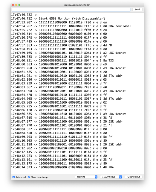
There is also an output of printable characters now which make debugging even easier. The output looks like this:
That looks a loot better. The only thing which is still a bit tricky is that the 65C02 supports an execution pipeline aka out of order execution.
If you read the source code closely you might wonder about the READY pin which is read and printed as well. Sadly that doesn’t work as expected. READY is and bidirectional pin which should be pulled up with a 3.3kΩ resistor. However the kit only contained 1kΩ resistors resulting in READY not being pulled down when the the 65C02 stops. I might see if I find some space on the breadboard to put three 1kΩ resistors in row and see if that works.
You find the source code for the Arduino monitor on GitLab: 6502Tutorial — Kit/Library
