Ben Eater 6502 Kit — Day 05 – Finishing the clock module
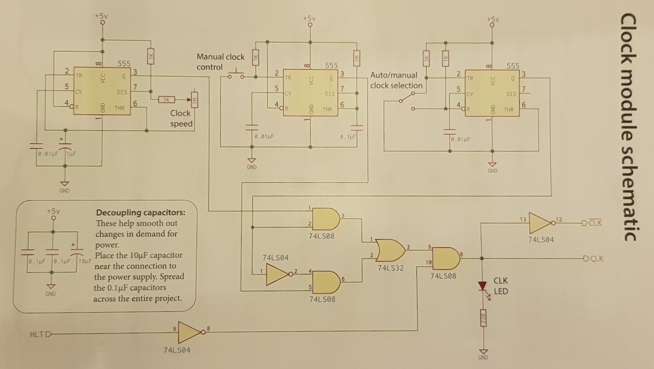
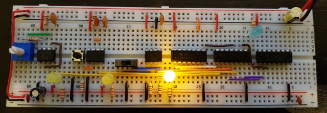
Day 5 and we are still building a clock. But today I finished the clock module. It was fun subproject. Tomorrow I start with the actual computer.
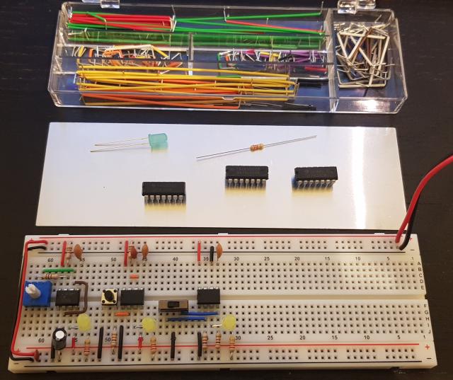
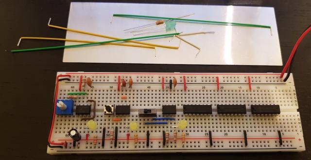
God that I compacted the placement of the 555 circuits yesterday. There is not much space left in the board.
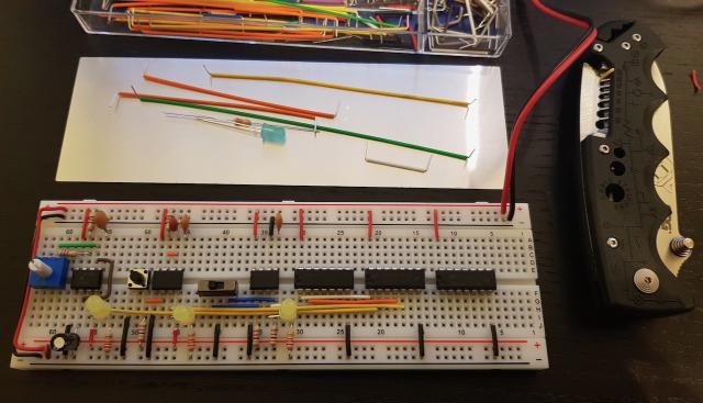
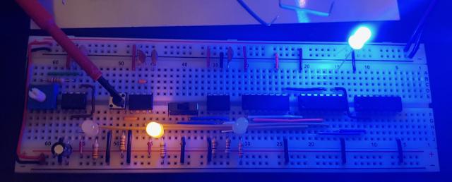
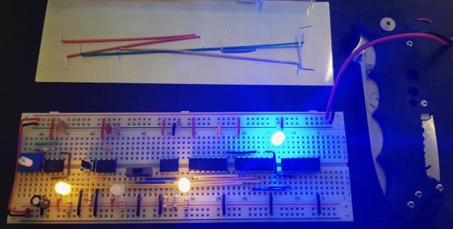
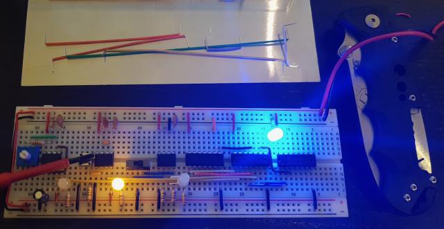
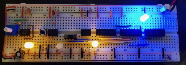
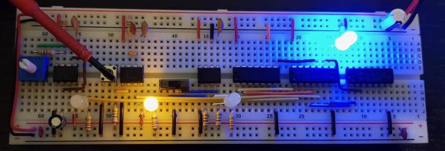
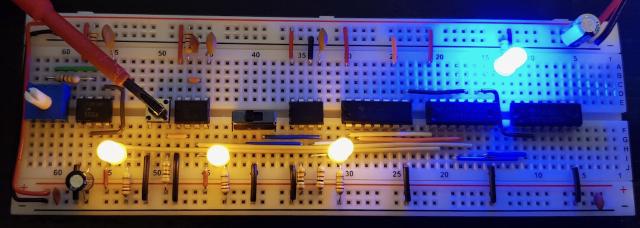
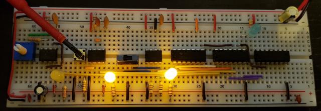
Yellow are the two clocks, white is the switch and orange is the inverted switch.
Everything seems to work. As in the original video I attached the LED without a limiting resistor. You can do this because the SN74LS08N has an internal resistor limiting the current. However that’s a fairly low resistor of only ≈100Ω making the LED far to bright.
I decided to add a 220Ω resistor to the blue LED like the yellow LED. Even with about ≈300Ω the blue LED is brighter than the yellow LED.
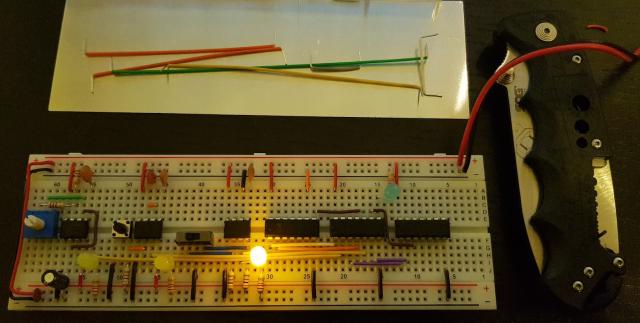
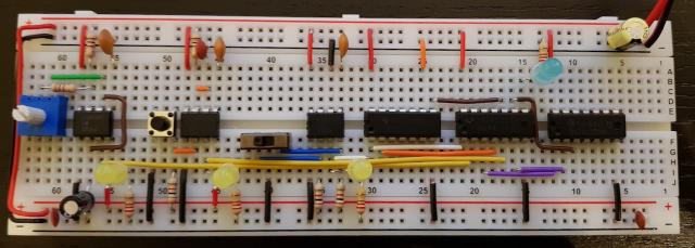
After the test I added the suggested decoupling capacitors. I left the yellow LEDs in place since the clock is will be used for the 65C02 project and not the 8 bit breadboard CPU project. After I added the capacitors i redid all the tests.
The LEDs from left to right:
- Adjustable clock
- Manual clock
- Switch, on = adjustable clock used, off manual clock used
- Blue LED final clock output.
